Conversion
Frequency Converters
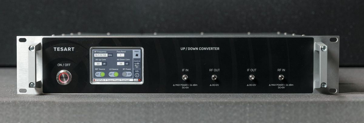
Rack-mount up/downconverters between L-band IF and C, X, Ku, Ka and Q-band, with low phase noise.
CXKuKaQ
Payload test · L / S / C / Ku / K / Ka
Measuring racks and software for testing spacecraft payloads in orbit, built to customer requirements.
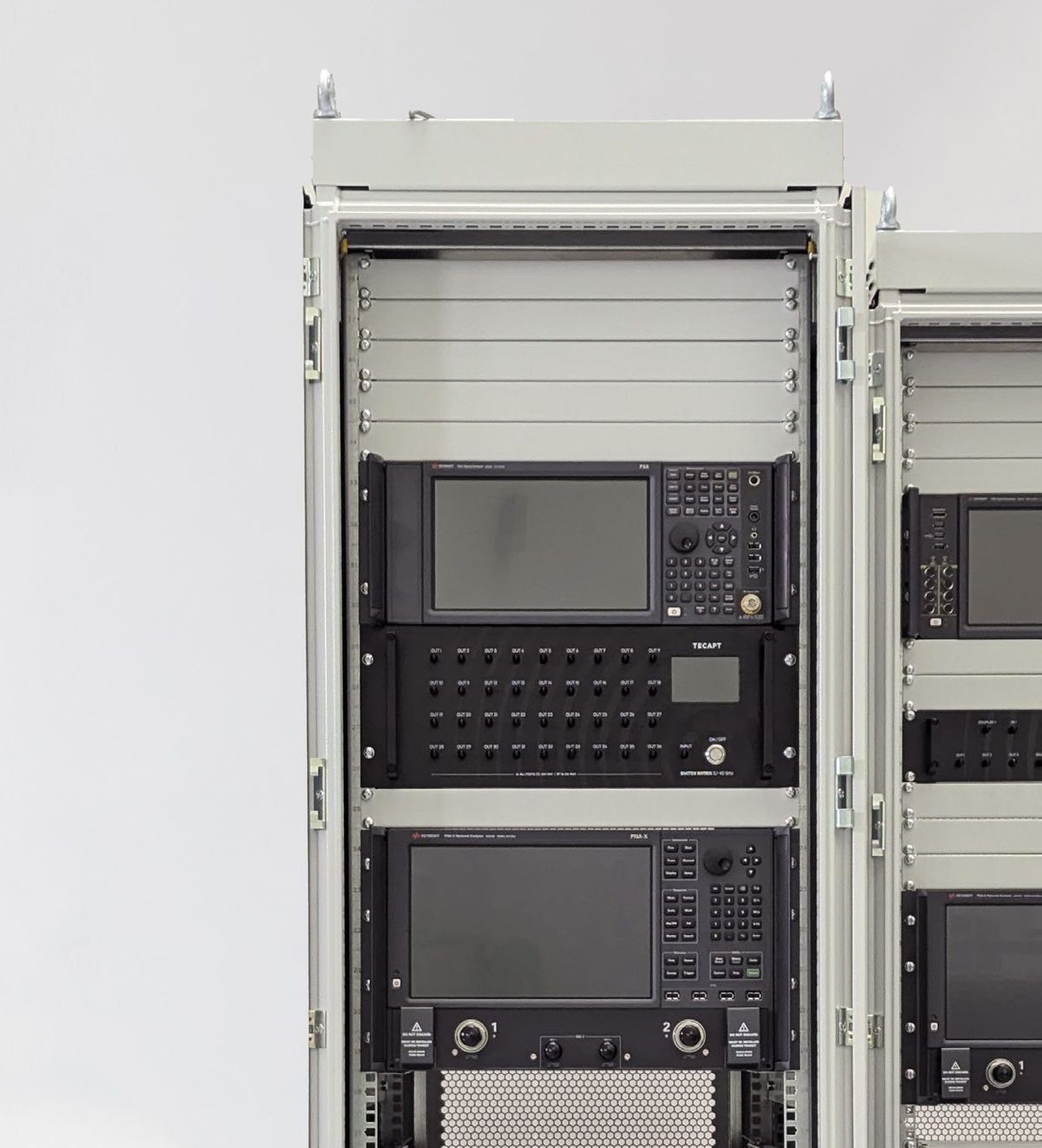
TESART develops payload in-orbit test (IOT) systems for testing spacecraft in orbit, covering a wide range of payload measurements during in-orbit testing. The system is a set of measuring instruments and other equipment integrated into racks and operated by a server running dedicated software. Depending on the task it may include measuring instruments, switch matrices, frequency converters, a GNSS (GLONASS) timing receiver, server and software, microwave cable kit and other equipment.
Measuring instruments
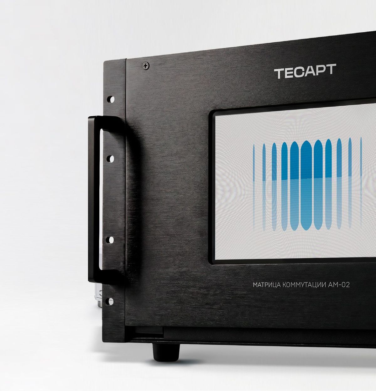
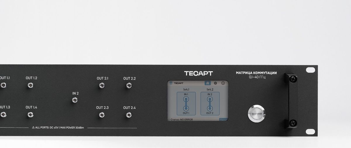
Switch matrices
Frequency converters
GNSS (GLONASS) timing receiver
Server and dedicated software
Microwave cable kit
Other task-specific equipment
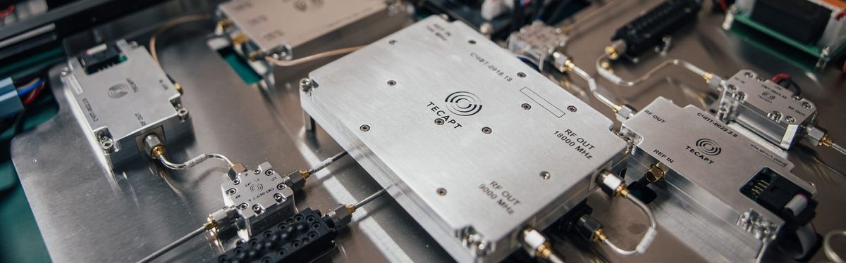
Automated verification of payload characteristics during in-orbit testing
Measurements during the outgassing phase across all Ka-, Ku- and S-band transponders
Storage of factory (ground) test data required for the checks
Downlink spectrum monitoring of payload channels
Power measurements of received signals using built-in instrument functions
Processing, visualization and storage of RF test results and spectrum monitoring data
| Parameter | Value |
|---|---|
| Transmit paths frequency range ¹ | 950–2000 MHz |
| Injection paths frequency range ¹ | 950–3000 MHz |
| Receive frequency range ¹ | 950–3000 MHz |
| RF ports | 2 transmit · 3 injection · 4 receive |
| Power supply | Single-phase AC, three-wire with protective earth, 220 V ± 20 V |
| Power consumption | ≤ 3.2 kW |
| Dimensions (L × W × H) | ≤ 1087 × 597 × 2019 mm |
| Weight | ≤ 300 kg |
| Measurement | Measurement uncertainty ² |
|---|---|
| G/T | 1.5 dB |
| Saturated EIRP per transponder | 1.4 dB |
| Saturation flux density (SFD) per transponder | 1.4 dB |
| AM/AM characteristic | 1.4 dB |
| Transponder gain-step range and limits | ≤ 1 dB |
| Transponder in-band frequency response | ≤ 1.4 dB |
| Beacon translation frequency and frequency error | ≤ 150 Hz |
| Receive/transmit antenna patterns | ≤ 1.4 dB |
| Selectivity | ≤ 1 dB |
| Beacon EIRP | ≤ 1.4 dB |
¹ Other bands are covered with optional TESART frequency converters. ² Excluding uncertainty contributed by the payload itself. Specifications subject to change without notice.
Every IOT system is configured for the customer's spacecraft and ground infrastructure: the mix of measuring instruments, switch matrices, frequency converters and software is selected per project.
Discuss your IOT requirementsConversion
Rack-mount up/downconverters between L-band IF and C, X, Ku, Ka and Q-band, with low phase noise.
Ground segment RF
Any-to-any or custom switching architectures, 8×8 to 16×64 and custom sizes, 500–2500 MHz, 50 or 75 Ω.
Signal routing
Electromechanical coaxial switch matrices, DC–40 GHz, up to 64×64, low insertion loss and high isolation.
Partnership & enquiries
Send us your frequency band, power level and interface requirements. Our RF engineers will propose a configuration and share datasheets.