Uplink
High-Power Amplifiers
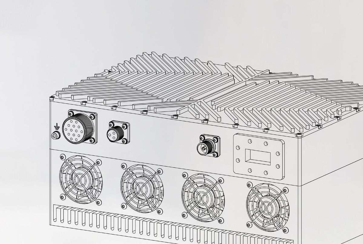
Solid-state transmitters from 100 W to several kilowatts, backed by local service and spares.
LCXKuKa
BUC0206 series · Outdoor
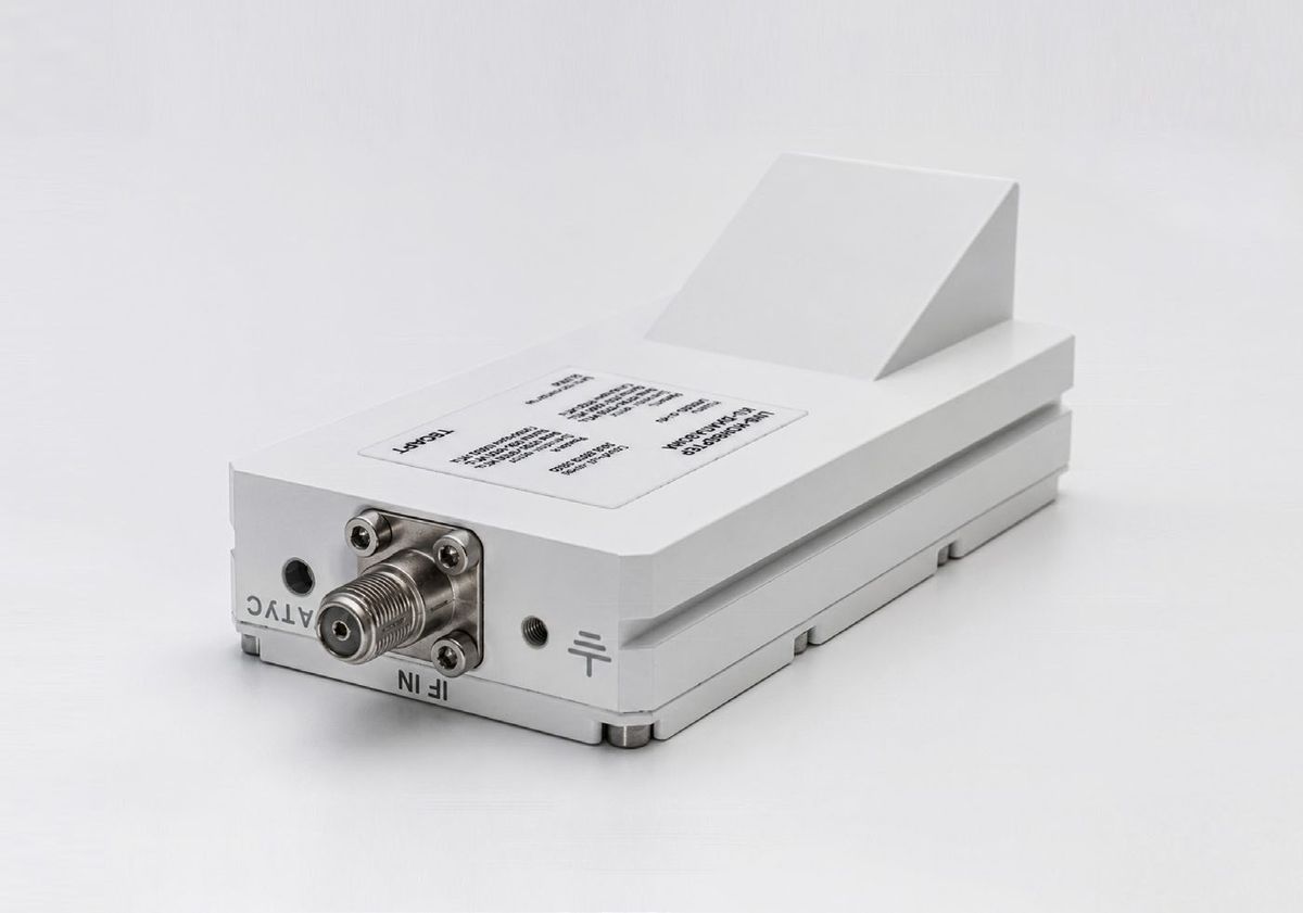
Outdoor block upconverter for satellite uplinks: L-band IF in, 5.725–6.525 GHz out, with full remote monitoring and control over Ethernet.
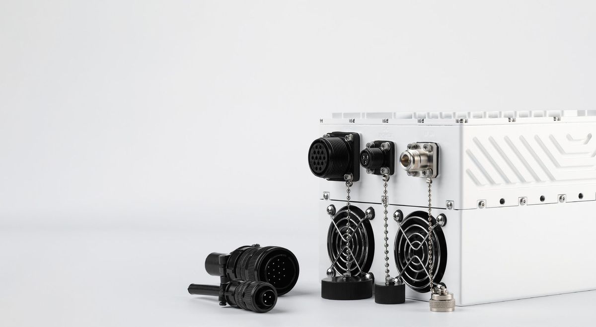
Covers the standard C-band uplink (5.925–6.425 GHz) within a 5.725–6.525 GHz output range
Five power classes from 25 W to 100 W in one mechanical platform
30 dB gain control in 0.5 dB steps; RF mute and built-in self-test
Automatic lock to an external 10 MHz reference delivered over the IF cable
Remote M&C: SCPI over Ethernet, web GUI, SNMP, RS-232/RS-485
Overdrive, temperature and fan status monitoring
| Model | Psat, min. | Psat, dBm |
|---|---|---|
| BUC0206-25W-C1 | 25 W | +44.0 dBm |
| BUC0206-40W-C1 | 40 W | +46.0 dBm |
| BUC0206-50W-C1 | 50 W | +47.0 dBm |
| BUC0206-80W-C1 | 80 W | +49.0 dBm |
| BUC0206-100W-C1 | 100 W | +50.0 dBm |
Custom frequency ranges and power levels on request.
¹ Gain does not fall below the nominal value over the operating temperature range. ² At 3 dB output back-off from Psat. ³ Two-tone, 5 MHz spacing, total output 3 dB below Psat. ⁴ With waveguide isolator installed. Specifications subject to change without notice.
Uplink
Solid-state transmitters from 100 W to several kilowatts, backed by local service and spares.
Conversion
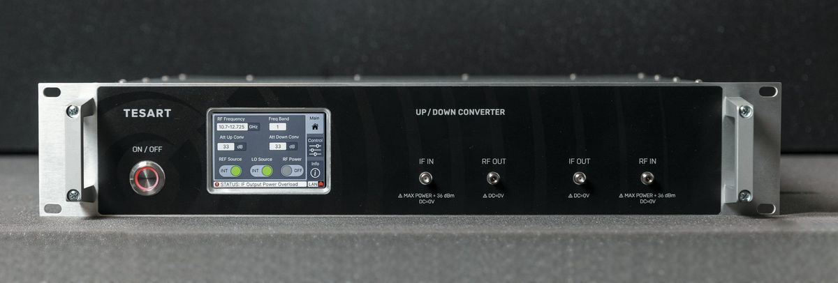
Rack-mount up/downconverters between L-band IF and C, X, Ku, Ka and Q-band, with low phase noise.
Downlink
Dual-band 10.7–12.75 GHz, noise figure 0.9 dB typ., external 10 MHz reference.
Partnership & enquiries
Send us your frequency band, power level and interface requirements. Our RF engineers will propose a configuration and share datasheets.